


 Trade Login
 Your Account
 Basket
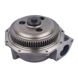
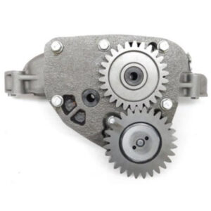
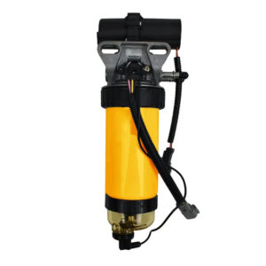
 Power Source Engine Parts Limited (Engine Fix UK) personnel have unsurpassed industry knowledge of designing, developing manufacturing and distributing OEM quality replacement Engine Lubrication Oil Pumps, Engine Cooling Water Pumps and Fuel Lift Pumps. We can offer a wide and comprehensive range of parts covering Light and Heavy Commercial Vehicles including Trucks and Buses, Off Highway Construction and General Industrial including Power Generation, Marine and Material handling and Agricultural applications.
All pumps are supplied with the necessary Gaskets and O rings and fitting instructions for installation of the pump onto the engine. Our products are designed and manufactured to match and in some cases surpass the OEM flow and pressure requirements, ensuring that the pump yields the correct flow characteristics and operating pressures throughout the engine operating range.
All our products undergo 100% testing to ensure that we give to our customers’ optimum product performance ensuring our products provide the necessary reliability, durability and longevity of operation for the engine. The lubrication oil pump range we offer lubricate, cool and fuel the world finest diesel engines from 1.5 to 30 litres capacity. We also specialise in supply of higher-pressure charge pumps used in industrial transmission.
All the products we provide have been designed and developed by our engineering department who use 3D Solid Edge CADCAM software, we also conduct considerable bench testing both performance and durability to ensure that our products will exhibit the required performance, reliability and durability when fitted to the engine and vehicle application.
Lubrication Oil Pumps
The pump in an engine circulates engine oil under pressure to the rotating bearings, the sliding pistons and the camshaft of the engine. This lubricates the bearings allowing the use of higher-capacity bearings and assists in the cooling of the engine. The Oil Pump is generally always mounted low – down, either submerged or around the level of the oil in the sump. A short pick-up pipe with a simple wire mesh strainer reaches to the bottom of the sump.
Failing to properly lubricate the engine will result in engine failure, oil flow through the oil filter and sometimes an oil cooler before going through the engine’s oil passages and being dispersed to lubricate pistons, rings, springs, valve stems and more. In general terms the oil pressure generated should be between 55 to 80 psi, local pressure (at the crankshaft journal and bearing) is far higher and set by the pump’s internal or external relief valve. All engines are ‘open systems’ because the oil returns to the oil sump by a series of controlled leaks, excessive bearing clearance increase the pressure loss between the first and last bearing on the crankshaft.
To ensure that the oil pressure does not exceed the rated maximum particularly on cold start up once pressure exceeds a pre-set limit a spring loaded pressure relief valve dumps excess flow /pressure to the suction side of the pump if the relief valve is internal recirculation or directly back to the sump if the relief valve is of external recirculation design.
Low Oil Pressure
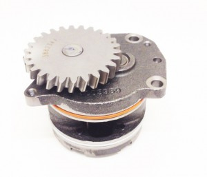 Low Oil pressure can cause engine damage, the low oil pressure can be caused by a faulty pump, such as a clogged oil pick up pipe, excessive wear on the pump due to high mileage, faulty relief valve which is stuck open.
The leading cause of low oil pressure in an engine is wear on the engine’s vital parts. Over time, engine bearings and seals suffer from wear and tear. Wear can cause these parts to eventually lose their original dimensions, and this increased clearance allows for a greater volume of oil to flow over time which can greatly reduce oil pressure. For instance, .001 of an inches worn off of the engine’s main bearings can cause up to a 20% loss in oil pressure. Simply replacing worn bearings may fix this problem, but in older engines with a lot of wear not much can be done besides completely overhauling the engine.
Particles in the oil can also cause serious problems with oil pressure. After oil flows through the engine, it returns to the oil pan, and can carry along a lot of debris. The debris can cause problems with the oil pickup screen and the oil pump itself. The holes in the oil pickup screen measure about 0.04 square inches (0.26 cm2). Holes of this size only pick up bigger pieces of debris and allow a lot of smaller pieces to flow through it. The holes in the screen are so big (relative to debris) because at low temperatures and slow engine speed the oil is very viscous and needs large openings to flow freely. Even with these large holes in the screen, it can still become clogged and cause low oil pressure. A .005-inch-thick (0.13 mm) coating on the screen can reduce hole size to about .03 square inches (0.19 cm2), which in turn reduces the flow of oil by 44 percent.
Even after passing through the oil pickup screen and the oil filter, debris can remain in the oil. It is very important to change the oil and oil filter to minimize the amount of debris flowing through your engine. This harmful debris along with normal engine wear in high mileage engines causes an increase in clearances between bearings and other moving parts.
Low oil pressure may be simply because there is not enough oil in the sump, due to burning oil (normally caused by piston ring wear or worn valve seals) or leakage. The piston rings serve to seal the combustion chamber, as well as remove oil from the internal walls of the cylinder. However, when they wear, their effectiveness drops, which leaves oil on the cylinder walls during combustion. In some engines, burning a small amount of oil is normal and shouldn’t necessarily cause any alarm, whereas burning lots of oil is a sign that the engine might need of an overhaul.
Wet and Dry Sump Systems
Conventional wet sump engines have one oil pump. It is generally located inside the lower part of the engine, usually below and/or to one side of the crankshaft. On dry sump engines, at least two oil pumps are required: one to pressurize and distribute the oil around the engine components, and at least one other ‘scavenge pump’ to evacuate the oil which has pooled at the bottom of the engine. This scavenge pump is sometimes (but not always) located in the ‘sump’ of the engine, and crucially, this scavenge pump’s flow-rate capacity must exceed that of the pump which pressurizes and distributes oil throughout the engine.
Disadvantages of dry sumps are increased weight, additional parts, and more chances for leaks and problems to occur.
Pump Design Features
There are generally two pumping types that are used on Diesel engines, these are:
Gerotor Pumps
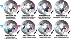 The gerotor is a positive displacement pumping unit consisting of just two elements: an inner rotor and an outer rotor or annulus. The outer rotor/annulus has one more tooth than the inner rotor and has its centreline positioned at a fixed eccentricity from the centerline of the inner rotor and shaft. A Gerotors sets come in a variety of geometric configurations, materials and sizes, all gerotor pumping sets have conjugately generated tooth profiles which provide continuous fluid-tight sealing during operation. As the gerotors rotate about their respective axes, fluid is drawn into the enlarging chamber to a maximum volume. As rotation continues, chamber volume decreases, forcing fluid out of the chamber. The process occurs constantly for each chamber, providing a smooth pumping action. The advantage of use of a gerotor set lies in its simplicity, versatility and performance. A gerotor pump requires minimal amount of machining and a small number of components to form the complete pump. The prime advantage of the gerotor set is that it can be produced a powdered metal sintered part which has the required accuracy and material properties such that machining of the pumping elements are minimal and no subsequent heat treatment of the gerotor is required.
For example, there are no expensive crescents to machine into the pump pocket, and compared to co-axial spur gear pumps, the gerotor design can eliminate a shaft and two bearings. A gerotor pump can be used in most applications where a co–axial gear or crescent pump operates up to approximately 300 psi. The versatility of the gerotor may be its greatest advantage. Gerotors can be mounted directly on an existing shaft or can be driven via the outer rotor. A gerotor’s size and geometry can be optimized for performance. The outside diameter, inside diameter, and length can be adjusted to create the smallest possible overall size, saving weight and minimizing power loss. Gerotors have a long service life because the relative velocity between the inner and outer element is very low. For example, when a gerotor assembly consisting of an 8-tooth inner rotor and a 9-tooth outer rotor is operating at 1800 rpm, the relative speed between the inner and outer rotors is only 200 rpm so wear will be minimal if oil condition is kept optimum by oil and filter changes to the recommended service intervals.
Application Requirements
 To match the oil pump to the engine, we need to determine the flow and pressure requirement for the engine. To determine minimum pump flow, the worst case is typically a combination of low speed, high pressure and high temperature so the pump flow is normally specified at engine idle speed on hot oil, at higher engine speeds there is normally a pressure relief valve which modulates the oil pressure at higher engine speeds such as rated speed, the relief valve opens and recirculates oil either internally within the pump or externally back to the sump of the engine.
Once the flow at a given speed has been determined, the gerotor’s theoretical displacement can be calculated making assumptions of the volumetric efficiency which can be as high as 95% at normal engine operating pressures of 60 psi but for higher pressures of 300 psi the volumetric efficiency can reduce to 70%.
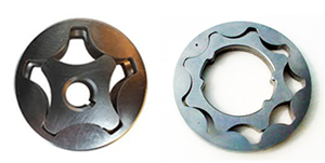
The gerotor sets show the typical range of sets available, the set on the right left side the 4/5 Gerotor set, the advantages of this system are:
- Smaller Dimensional Package
- Higher Operating Speed
- Less Power Loss, Higher Mechanical Efficiency
On the right hand side, the 8/9 gerotor set:
- Larger Dimensional Package
- Less Flow/Pressure Ripple
 Ability to accommodate greater shaft diameter such as engine crankshafts.
The dimensional constraints within the engine and the flow/pressure requirements will determine the optimum gerotor set to be used and the drive option for the oil pump. Generally, the drive options for the oil pump can be as follows:
- Pump can be driven by a gear within the engine drive gear train
- Pump can be driven via a skew gear drive form the camshaft
- Pump can be driven directly off the crankshaft
In the case of option drive option 1) the drive ratio of the gear can be used to optimise pump speed, the location of the pump centre-line height is normally set as low as possible in the engine to keep the prime height of the pump to a minimum, this will lead to the pump being better able to prime the oilways when the engine is cranked over prior to start up, often the optimum solution in this case is that the pump is mounted on the underside of the engine cylinder block and the pump sits within the sump pan making the prime a matter of inches.
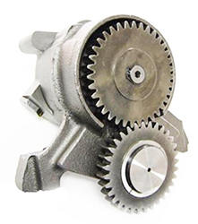
The pump shown below is an example of a gerotor pump which fits on the engine cylinder block front cover and fits within the engine sump pan, the example shown is fitted in the Ford Cargo Truck engine.
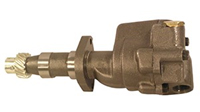 In the case of drive option 2) the oil pump is situated normally mid-engine at the bottom of the cylinder block but with an extended drive shaft with splines/hexagons that mates with a secondary drive a skew gear with mates with the gear on the camshaft, with this design the pump speed runs at half engine speed so the power losses are normally lower. Again as in option 1) the pumping chamber of the pump sits in the sump so the inlet and outlet pipework are simplified and again the prime height is kept to a minimum.
The oil pump shown below is an example of an oil pump driven off the camshaft, the pump shown if fitted to Ford Dorset and Dover engines.
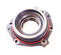 In the case of option 3) the oil pump is directly driven off the crankshaft therefore due to the inherent size of the crankshaft the inner gerotor has to accommodate a large shaft diameter so the gerotor will normally have a larger number of teeth and the outer gerotor will be larger in diameter. However, the crankshaft in a diesel engine is normally subject to both torsional and axial activity so this generally means that the choice of the gerotor materials needs to stipulate harder materials by either specifying higher density sintered materials or using supplementary heat treatments to produce a harder more durable material.
However, this design solution is generally not used on larger diesel engines as they are torsionally more active and the need for higher flow means that space at the front of the engine becomes a constraint. The advantage of this system is that you reduce the number of gears in the engine drive train and the prime height again is minimal.
The pump shown above is an example of an oil pump driven directly off the crankshaft, this pump is fitted to an International 466 engine.
Co-Axial Gear Pumps
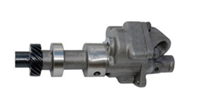
For Larger capacity diesel engines, the gerotor set principle has its limitation with regard to its flow capacity within the dimensional constraints, also the larger engines have higher loadings and as a consequence the better pumping principle to adopt is a co-axial gear type arrangement which enables the use of hardened gears with greater flow capacity and uplifted durability capability, generally these pumps have more components within and are therefore more expensive to manufacture. The pump generally consists of two meshed spur gears or helical gears enclosed in a housing.
There is very little clearance between the gear teeth and the housing. One gear is attached to a shaft which is driven through suitable gears from the camshaft or the crankshaft of the engine. The other gear (Idler Gear) is free to rotate on its own bearings. When the pump is in action, the oil is driven between the gear teeth from the inlet side, carried around the between the gears and the pump housing and forced out of the outlet side. The quantity of oil supplied by the pump depends on the size of gears and the speed of rotation of the gears.
The pump shown above is an example of a co-axial gear pump driven by a skew gear directly off the camshaft in this case on a Fordson Major engine. The pumps shown below are examples of a Detroit oil pumps that bolts up to the base of the cylinder block and sits in the engine sump pan and a Cummins pump which is driven higher up the engine from within the engine gear train.
Transmission Oil Pumps
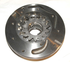 Engine Fix UK manufacture a range of transmission oil pumps which fit in Industrial Off Highway Transmissions, these charge pumps actuate the transmission and as a consequence are required to work at higher operating pressures. Typically a engine oil pump will operate at 80-100 psi whereas a transmission pump will operate at 200-400 psi.
To generate these higher pressures the pumps generally are of higher tooth gerotor set or a crescent type principle. In most cases the oil pump is situated close to the torque converter although in some cases the pump can be independently driven higher up the transmission. The higher pressure requires greater precision of the pumping members and generally the running clearances are minimal. The use of a high number of gear teeth means that the pressure ripple is kept to a minimum to ensure there is no hydraulic noise developed in the transmission. Shown to the left is a simple schematic of how a crescent pump works.
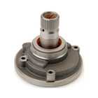
Liquid enters the inlet port between the rotor (large exterior gear) and idler (small interior gear) teeth, the arrow indicate the direction of the pump and the oil within it. The oil travels through the pump between the teeth of the “gear-within-a gear” principle. The crescent shape divides the oil and acts as a seal between the inlet and outlet ports. Intermeshing gears of the idler and rotor form locked pockets for the oil which assures high volumetric efficiency. The rotor and idler teeth mesh completely to form a seal equidistant form the outlet and inlet ports. This seal forces the oil out of the outlet port. The photo graph below shows the typical internal machining characteristics of a crescent pump used in industrial transmissions.
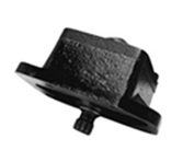
Shown above is a typical charge transmission pumps used in JCB, Caterpillar, Case Manitou, Hyster, Massey and Ford applications where a torque converter is integral with the transmission pump drive. To the left is an example of a Transmission pump which is cited independent of the torque converter.
Water Pumps
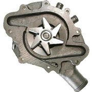
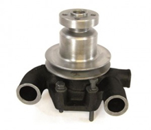 Our engineering knowledge in the design, development and manufacture of water pumps for diesel engines is considerable with over 100 years accumulated knowledge of the product and its applications, our experience covers diesel engine from 1.5 litres through to 65 litres. Our water pumps are designed for the particular model of engine you have, each one has undergone extensive testing and evaluation to ensure it works time after time and delivers the right amount of coolant flow to effectively cool your engine. The role of a water pump in an engine is primarily to regulate its temperature and to prevent an engine from overheating. It pumps water and coolant through the engine block and cylinder head via a series of pipes, drawing out the heat generated, before going into the radiator. The coolant temperature should not exceed 110 Deg C to prevent damage to the engine internal components.
Engine Fix Water Pump Range – Always in Stock
Water pumps tend to be highly reliable components, the recommended inspection/maintenance interval is once every 2,000 hours of service. Expectation is that you would expect them to last between 8,000-10,000 hours but occasionally they can malfunction. In the unlikely event of failure replacing them is straightforward and Engine Fix UK offer a comprehensive range for your needs. Regular maintenance by replacing the pump before it fails can prevent your engine from overheating, seizing up and ultimately suffering expensive failures.
Our water pumps include with them all the gaskets and seals required to fit the water pump to your engine.
Engine Fix UK ensure that we optimise our pumps to yield the correct coolant flow and pressure to ensure adequate cooling of your engine. This is achieved by using the correct impellor shape and design, impellor size, smooth surface treatments and correct drive ratio using pulley/gear ratio. Our pumps include the following design features.
- High Quality Cassette Seals using the latest long-life materials.
- Sealed bearings to give extended service life.
- 100% leak testing prior to despatch.
- Detailed fitting instructions
Water Pump –Technical Characteristics
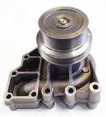 All pumps are very similar in design, with the following differences:
- The shape, size and materials of the water pump housing. In the case of the diesel engine the bulk of water pump housings are made from Cast Iron, although in some engines where weight is a concern aluminium can be used. The water pump is generally fitted in the cylinder block at the front of the engine or externally mounted.
- The types of bearings used to carry the loading from the water pump and drive line.
- The types of mechanical seal fitted.
- The type of drive used normally belt driven or gear drive.
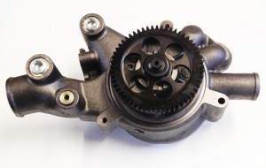 The water pump will either be driven via a pulley either mounted directly on the water pump shaft or a stamped steel pulley bolted to a hub again on the water pump shaft, on early engines the pulley is normally a single or twin vee-groove, for later engines with the introduction of poly vee-belts multi grove pulleys are now used. With the advent of tighter emissions regulations later generation engine was designed with the water pump drive a gear in the main engine drive train.
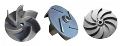
The rear of the water pump will have an impeller fitted, this item pumps the water around the engine, the impellor materials is cast iron although with the drive for greater flow and improved efficiency water pumps impellors are now made out of stamped steel, glass filled nylon or resinoid materials.
 The impellor and drive line loads are taken by the use of bearing, which can be one of several different types of dependant on the design of the water pump. For small or older diesel engines generally, the bearing fitted is an integral shaft bearing which contains both the ball roller bearing arrangement around a spindle, the bearing is sealed for life. This bearing is used because of their advantage in terms of cost simplicity and performance. Although in recent years integral shaft bearings have been developed with larger cage diameters to support higher load. In large water pumps fitted to older engine the bearings are normally a pair of deep groove ball bearings with spacing between them set by a distance piece with the bearings mounted on a hardened steel shaft. Again the ball bearings are sealed for life using synthetic seals at either end of the bearing to provide positive sealing at all times and preventing the ingress of dirt. Where high axial and radial loads are encountered tapered roller and angular contact bearings are used.
 The impellor and drive line loads are taken by the use of bearing, which can be one of several different types of dependant on the design of the water pump. For small or older diesel engines generally, the bearing fitted is an integral shaft bearing which contains both the ball roller bearing arrangement around a spindle, the bearing is sealed for life. This bearing is used because of their advantage in terms of cost simplicity and performance. Although in recent years integral shaft bearings have been developed with larger cage diameters to support higher load. In large water pumps fitted to older engine the bearings are normally a pair of deep groove ball bearings with spacing between them set by a distance piece with the bearings mounted on a hardened steel shaft. Again the ball bearings are sealed for life using synthetic seals at either end of the bearing to provide positive sealing at all times and preventing the ingress of dirt. Where high axial and radial loads are encountered tapered roller and angular contact bearings are used.
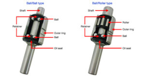
Integral shaft bearings are shown below:
Divided into 2 types by internal features: double-race-ball type(ball/ball) and ball/roller type. Load resistance is the principal difference of “ball” from “roller”. “Ball” locating on a “spot” excels in low noise at high speed. “Roller” in linear support endures more radial load and increases load rating. “Roller” is preferred in driving pulley and/or when a load, such as a fan coupling, is installed at off-set position in front.
 Divided into 2 types by internal features: double-race-ball type(ball/ball) and ball/roller type. Load resistance is the principal difference of “ball” from “roller”. “Ball” locating on a “spot” excels in low noise at high speed. “Roller” in linear support endures more radial load and increases load rating. “Roller” is preferred in driving pulley and/or when a load, such as a fan coupling, is installed at off-set position in front.
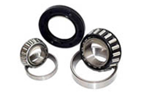
Deep Groove Ball Bearing is shown below right and Angular Contact Bearings are shown below left:
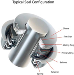 A water pump seal is used to seal off the water passageways of the water pump from the bearing arrangement, in early designs of water pumps the water pump seal was two separate parts, the rotor being fitted in/on the impellor and the stator was fitted in the water pump housing, these seals were generally unreliable and the seal industry developed the cassette seal. The seals initially were available in rubber or stainless steel. The advantage of using this seal is that it is a sealed unit which can be leak tested and also cannot be contaminated with foreign matter on assembly into the water pump. The inner sleeve is in permanent contact with the shaft stopping the possibility of coolant passing between the impellor and shaft. The rubber version of the cassette seal requires the impeller to compress the seal to the correct working height, the steel version is assembled in the water pump by using a fixed assembly tool. Engine Fix UK fit all our pumps with the steel cassette type seal to give to our customers the optimum seal performance to ensure long life for the water pump. The cassette seal materials can be optimised depending on the water pump application. Normally the rotor material of the seal with be ceramic, although where long life is required a silicon carbide option can be offered. For the stator part of the seal this is normally hard carbon although again if the water pump is working under extreme conditions a silicon carbide can be offered. For gear driven pumps the cassette seal adopts a positive drive approach to ensure that the seal can cope with the gear torsional activity without failure. The rubber elements within the steel are normally HNBR material but again for higher temperatures a HSN material can be offered.
Common Modes of Failure for Water Pumps
The two most common causes of failure of a water pump are:
Bearing Failure
Initial failure is normally indicated by an increase in noise of the bearings, if the water pump is run continuously in this condition the bearings start to disintegrate causing terminal failure to the water pump with potential loss of engine coolant causing damage to engine. The failures can be due to the following causes.
- Natural wear and tear caused by excessive engine hours of running.
- Over tensioning the vee-belt overloading the bearings
- Excess radial loads caused by belt failure on Poly–vee multi belt pulleys.
- Out of balance fan assembly’s or pulleys
- Lack of or escape of grease from the bearing.
- Incorrect fitting of bearings during manufacture causing damage to the bearing internals
- Seal failure washing away bearing lubricant.
Water Pump Seal Failure
The indication of seal failure in the water pump is initially identified by coolant loss from the weep hole in the housing, if this water loss is ignored ultimately the seal will move to failure with loss of water/coolant form the cooling system and overheating of the engine should the temperature warning gauges/switches are ignored.
The most common causes of seal failure are:
- Natural seal wear due to high hours running.
- Running the engine without water in the cooling system
- Bearing failure causing the seal to leak
- Allowing the coolant to freeze and running the engine.
- Leaking head gasket or piston rings creating excessive pressure within the cooling system
- Dirty coolant of overdosing of additives to the cooling system
- Lack of coolant or use of contaminated water
- Incorrect fitting of the seal during manufacture
Fuel Lift / Fuel Transfer Pumps
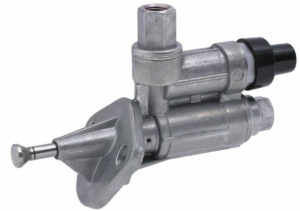
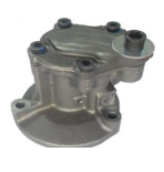 Fuel Lift pumps bring fuel at low pressure from the fuel tank up to the higher-pressure injection pump via fuel filters the pumps are designed to provide initial fuel pressure at the correct flow rate & pressure to prevent cavitation and vaporisation of the fuel which can lead to damage, generally this type of fuel lift is a diaphragm pump are used on older generation engines. OEM manufacturers then moved to plunger type lift pumps which were more reliable and driven off the camshaft.
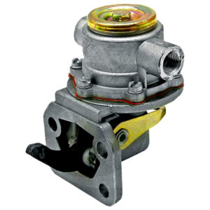 Modern day diesels have moved to common rail engines which use either electric or vacuum pumps to deliver fuel to the injection pump. Also, a number of truck engines now use a unit injector system whereby the injector nozzle and the injection pump are combined in a single component, the fuel transfer pump that feeds fuel from the tank to the unit injectors is a gear pump generally mechanically off the camshaft. This high pressure injection system delivers power, fuel consumption & improved emissions over the earlier lower pressure fuel injection by injecting fuel as a larger number of smaller droplets, giving a much higher ratio of surface area to volume. This provides improved vaporisation from the surface of the fuel droplets and so more efficient combining of atmospheric oxygen with vaporised fuel, delivering more complete and cleaner combustion.
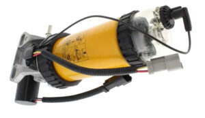 All the Truck OEMs now use this system namely Deutz, Iveco, Mercedes, Renault, Volvo. Also on smaller engines OEMs have developed electrically driven fuel pumps.